Tree / Digital Prototyping
The KnifOne
My master craftsman thesis, a phone case with a Swiss-army-style tool module, rebuilt from the original SolidWorks files for the browser, without SolidWorks.
- Status
- Green · Released
- Hours
- about 37
- Tokens
- about 12 M
My master craftsman thesis design now opens as a full 3D viewer in any browser, with its real CAD data, its motions and the whole thesis, and without SolidWorks.
In this article
A multitool that only SolidWorks could open
This port exists so that I can finally present the project well and show a 3D model online, instead of only in SolidWorks.
The KnifOne began as a question in my master craftsman thesis: the smartphone is the most compact digital companion we have, a Swiss pocket knife is one of the most compact mechanical ones, so what does a single object look like that keeps the advantages of both? The thesis answered with a virtual prototype. A realistic 3D model and its presentation were the agreed scope, and analysis, optimisation and realisation were left out on purpose. The process chart in the thesis has a marker that says "Project END" right after design, before the finite element stage.
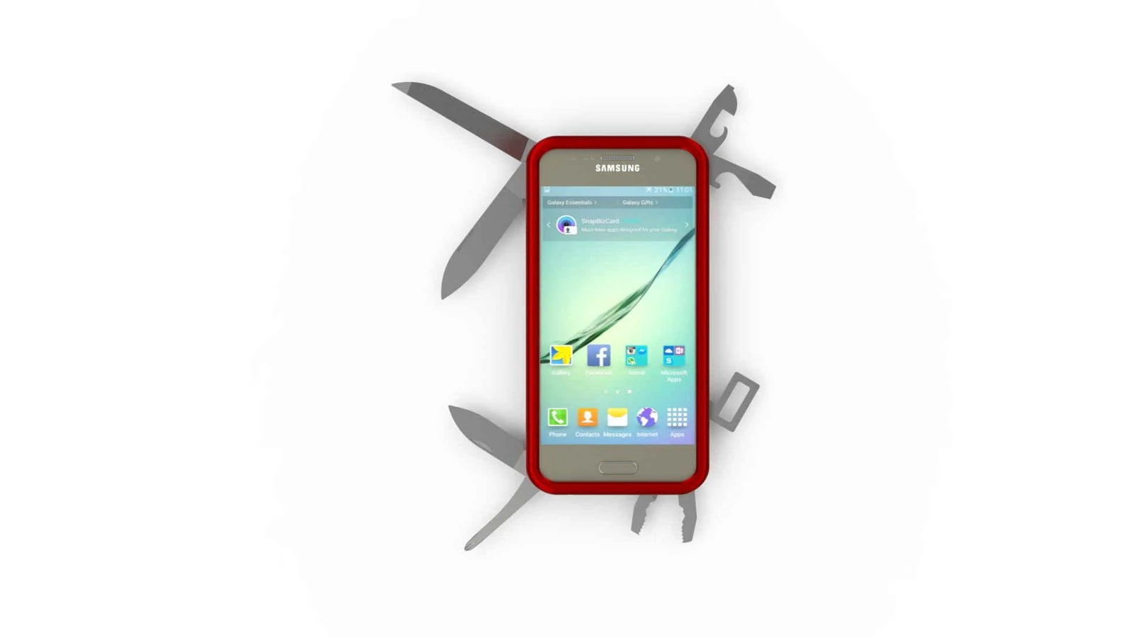
So the gap is really two gaps. The product never left the screen, and the thesis says why: accessory makers learn a phone's dimensions only a few months before release, the shape changes every year, and an elaborate case cannot follow that pace. I wrote that a realisation could only be considered once a modular phone like Project Ara reached the market. The second gap is the one this project closes. Everything I had built sat in SolidWorks part files, renderings and a PDF. Without SolidWorks nobody could turn the model, fold out a blade or look inside.
The goal of the port: open the real CAD data in any browser, with the real motions and configurations of the construction, from a plain static site with no CDN, no server code and no CAD program anywhere in the chain.
What I constructed
My own motive in the thesis was the technical challenge of learning a 3D design program from scratch while studying current phones, accessories and Victorinox tools. Rough sketches and paper models came first, then the 3D program.
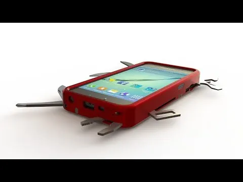
The reference phone had to have its camera in the middle, because a corner camera would cost a corner of tool space, and no speakers on the back. The Galaxy S6 fit, and I bought a ready 3D model of it. That phone model is not my work.
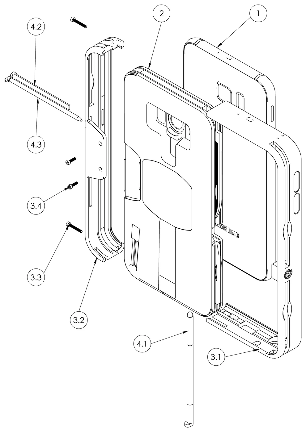
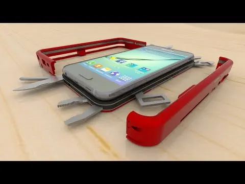
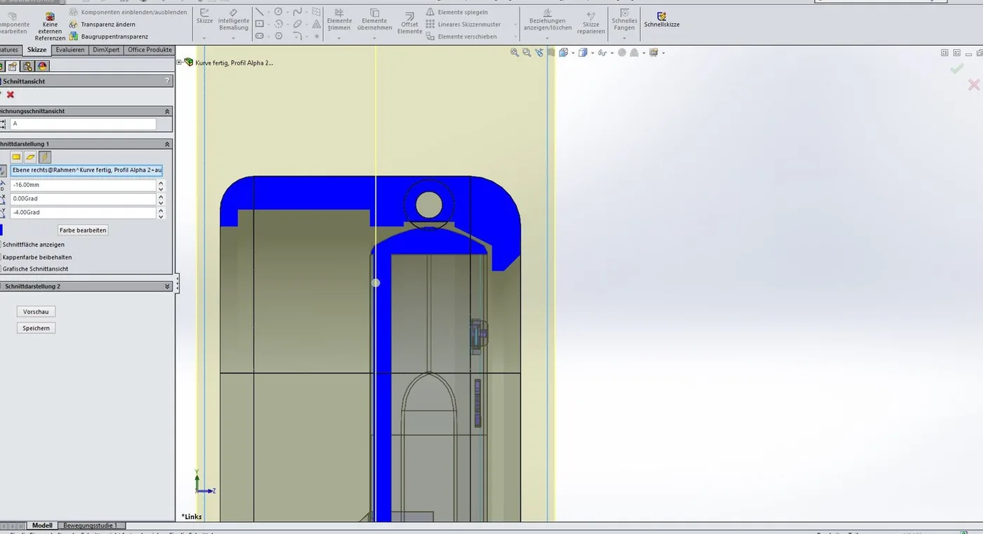
Around it sit two things. A two-part aluminium frame works like a screw-mounted bumper case: it slides on like a rail guide and is closed with four M1.4 socket screws. Rubber strips keep the metal off the polished phone. Behind the phone sits the module, built like a pocket knife in layers: aluminium back cover, thin aluminium liners, a polycarbonate middle layer that holds the tools, a bottom layer, and a felt coating that hides every rivet and screw and is kind to the phone's back.
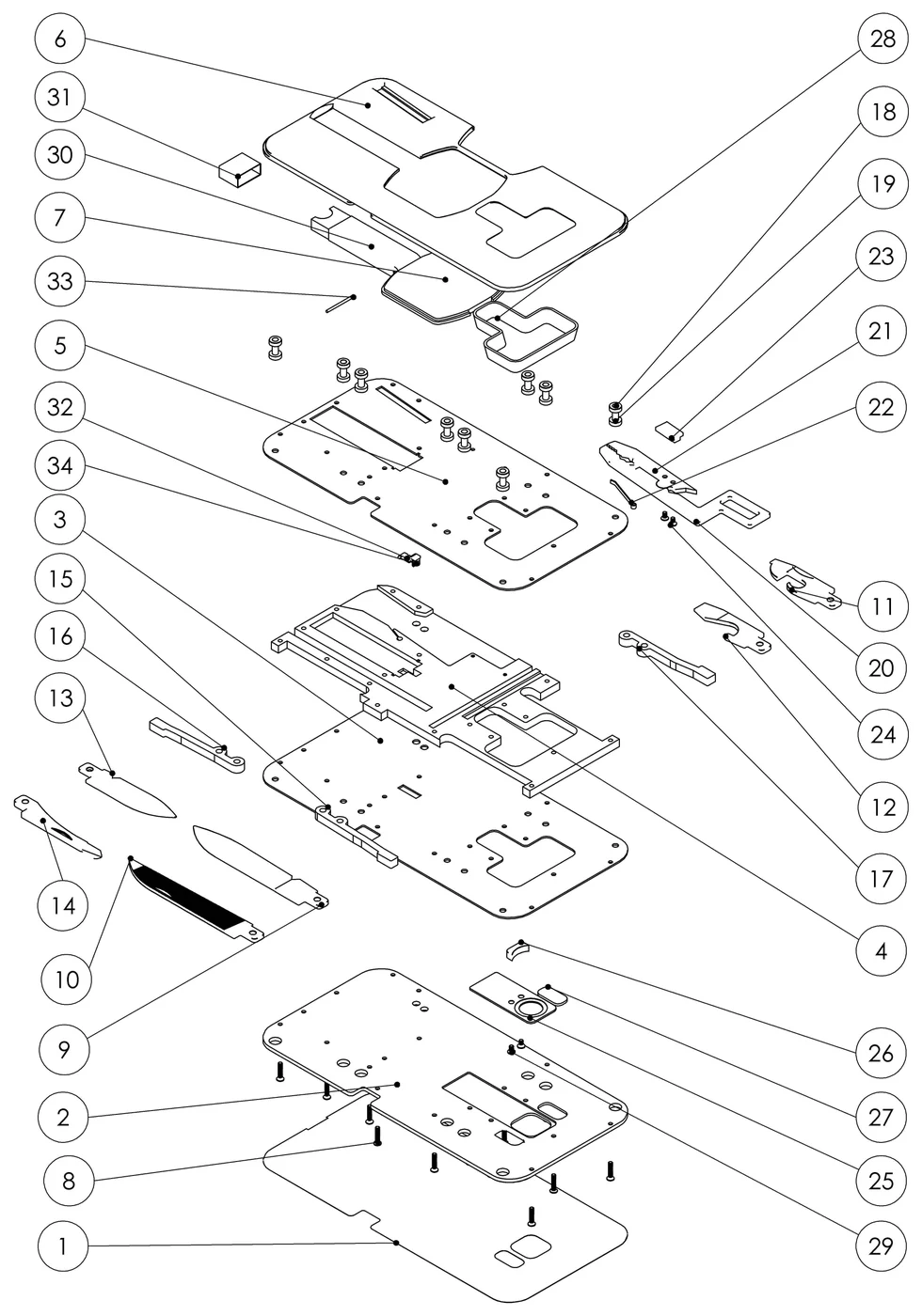
Sixteen numbered tools and functions came out of that:
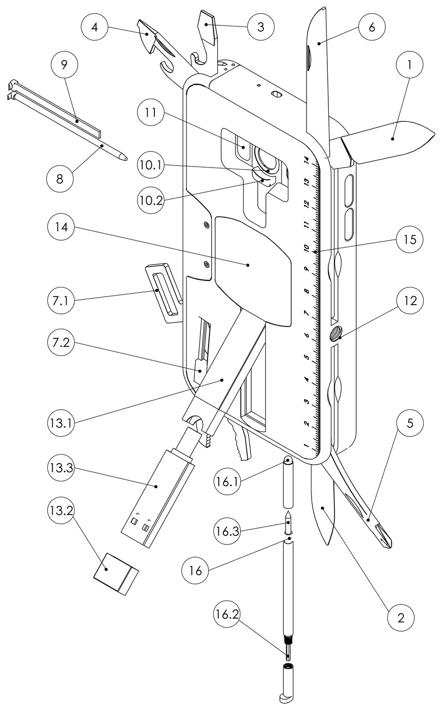
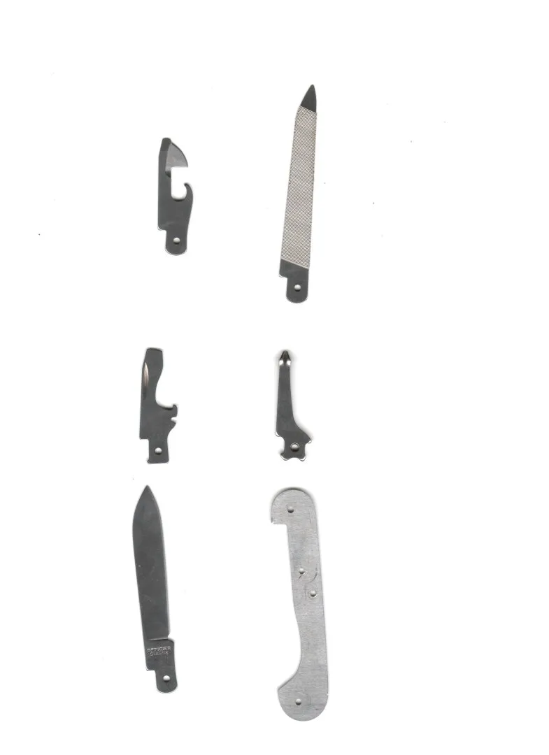
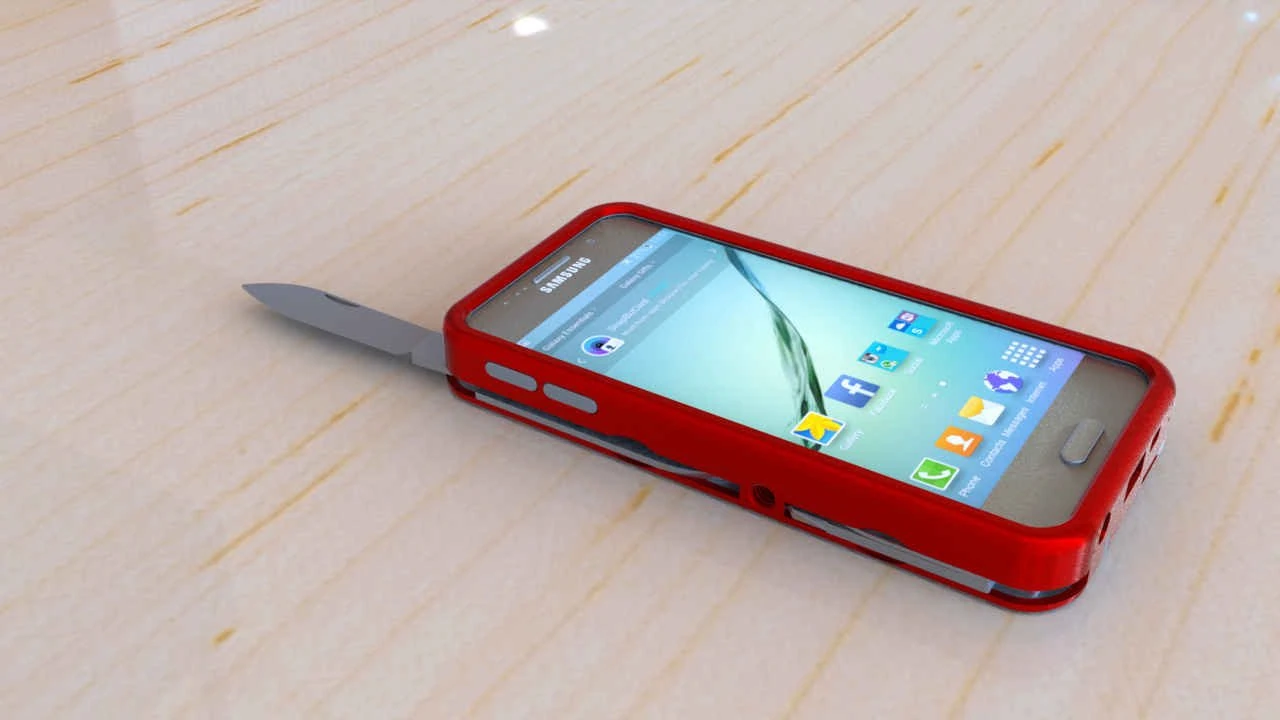
- Folding like a pocket knife: large blade, small blade, metal saw, Phillips screwdriver, can opener, bottle opener. Folding rather than sliding, and flush with the frame, was a rule I set myself. It took away most of the freedom a case normally has and made the frame one of the hardest parts of the design.
- Combination pliers that slide out instead of folding, because the folding pliers of a pocket knife force your thumb far outside the handle. They reach 20 mm and open 30 degrees.
- Plug-in parts: ballpoint pen, tweezers, and a stylus that unscrews into an Allen tool for the case itself and a scriber.
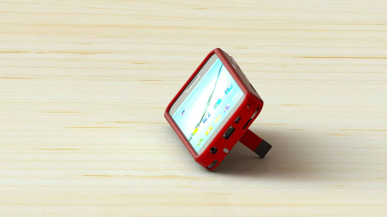
- For the phone: a kickstand with three detents for portrait and widescreen with a USB stick stored inside it, a sliding mechanism for magnetic fisheye lenses, a mirror, a quarter-inch Whitworth tripod thread, a metal plate for magnetic mounts, an embossed ruler, and flat frame sides so the phone works as a spirit level.
The thesis ends honestly: a build was possible in principle, but not at this scale for cost reasons, and a force analysis of the frame and a weight reduction would come first.
How the port works
The whole port stands on one fact: a SolidWorks part file keeps the display mesh it last showed on screen. Nothing has to be recalculated from the solid model, because a copy of the visible surface is already stored inside.
One command runs the chain from CAD files to a finished site:
- Read the containers and pull out each part's display mesh.
- Read materials and appearances, and split each mesh into face groups with their own material.
- Rebuild the assembly from the instance tree with its 4x4 transforms, once per configuration.
- Derive motions by comparing configurations.
- Merge all configurations into one model plus a small state file that says per view what is visible and which poses differ.
- Refine curved faces, compress, and build a static site.
The result is 86 parts, 34 configurations, 106 instances in the standard view, 124 across all configurations, and 72 material face groups. The viewer loads the model once, so a view switch is a change of state: one tool folds in while the next swings out, parts fade, the camera flies, nothing is downloaded. The deploy folder is 64 MB.
In the browser that gives 33 views in 7 chapters, each with its own camera, six standard views, 11 light presets, 10 metal presets, five frame finishes, contact shadows and a procedural wood table. There is a feature-tree part list with bill of materials badges and German or English names, a part panel with thesis data, a motion panel with hinged tools that stop at 135 and 180 degrees, and a guided tour of 18 keyframes. The tour includes the phone standing on its kickstand on a wood floor, with the pose solved numerically so that case edge and stand tip both rest on the floor.
The 62-page thesis sits inside the viewer, each part linked to its section and its position in the bill of materials, in German and in an English replica whose page N is page N of the original. A gallery tab holds the renderings, blueprints and construction stage screenshots.
Tools and libraries
No AI model is part of the product or the pipeline. Claude Code was the tool that built it.
- CAD reading: sldprt-export by XRTC5 (MIT) for block containers and the strip-table mesh decoder, olefile plus an own extractor for the older OLE containers, own readers for the material tree and for
.p2mappearance files. - Geometry: NumPy, trimesh for scenes and GLB export, fast_simplification for quadric decimation of the phone body, own code for the screw motions and PN triangle refinement.
- Compression: gltf-transform 4 with Draco.
- Rendering: three.js r170 with ArcballControls, GLTFLoader, DRACOLoader, RGBELoader, RoomEnvironment and BufferGeometryUtils, physical materials with clearcoat, anisotropy and iridescence, four HDRIs from the three.js example assets, ACES and other tone mappers. Everything ships locally.
- Thesis: PyMuPDF for text extraction and for the replica.
- Images: Pillow for icons and generated maps.
- Checks: scripted browser runs against the viewer, html5lib for parse errors, a test hook attached only in debug mode.
- Hosting: any static host, with cache and compression rules written by the build. It runs on Netlify.
What the CAD files did not say
Stale and missing geometry. The saved mesh is whatever SolidWorks last displayed. Some meshes were older than the part, and five parts never had a mesh in any copy. The bounding box the assembly stores for each part became the referee: meshes are clipped, scaled or moved onto it, additions are marked in the manifest as derived, and the five parts use named stand-ins.
Motion hidden in binary data. The original mates are binary, and the motion study holds only a handful of key times. But the construction has 34 configurations, and if a component sits differently in two of them, the mathematics says how it got there. Any rigid move is a screw motion: one axis, one angle, one slide (Chasles' theorem). A 180 degree turn is ambiguous, because plus and minus 180 end in the same pose and one path runs straight through the case, so the sense comes from a half-open configuration. The tripod view moves 102 parts at once, which is no real motion, so above 80 % moving parts the viewer cross-fades instead.
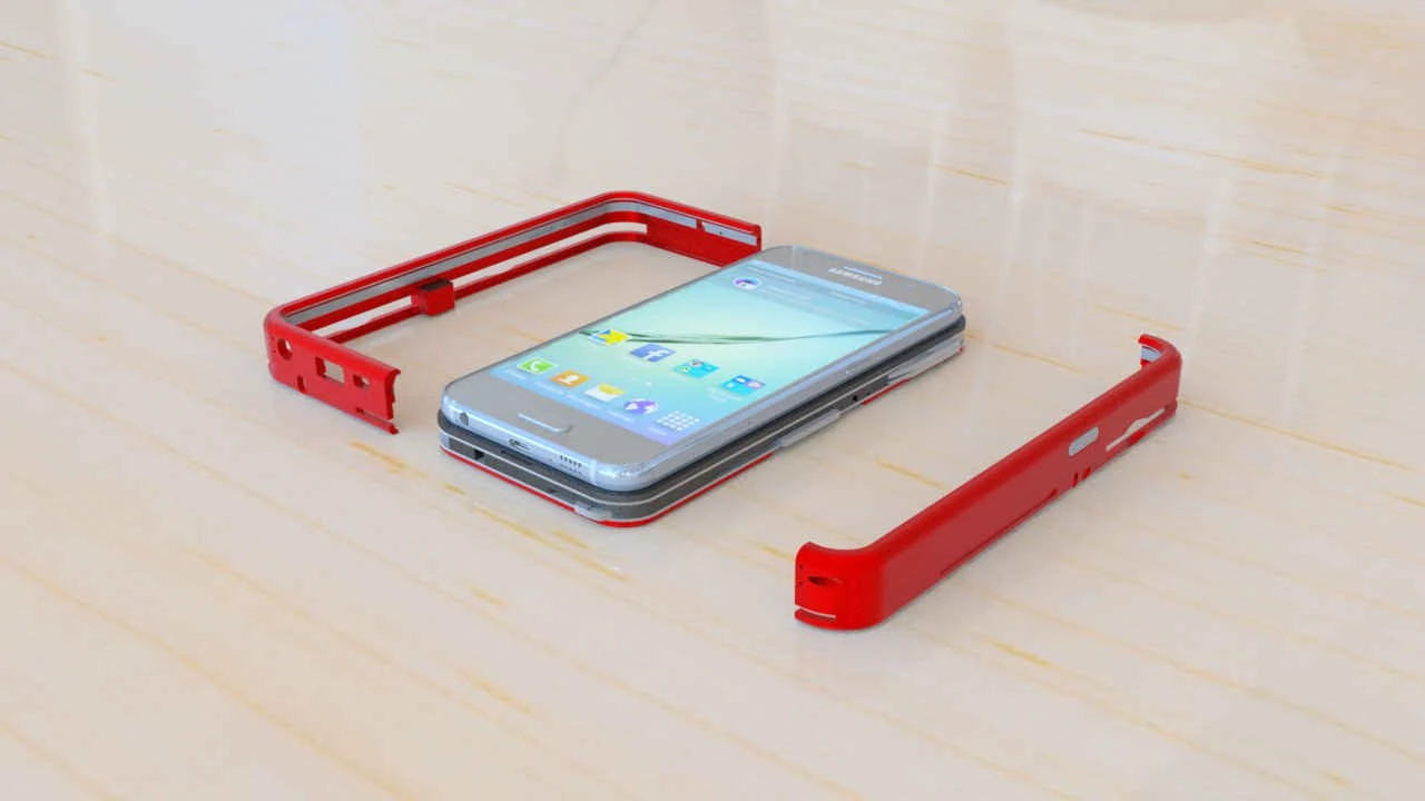
Materials without their source. The exact red of the case lived in a library file of the old installation, so it could not be recovered. Shader types come from the part files, parameters from stock appearance files, and on top sits a hand reconstruction per part from the renderings and RealView screenshots, checked against pixel values. Lenses needed the most care: what you see from outside is a flat disc, so it renders as glass with normals bent into a dome while the geometry stays flat.
Curves that are polygons. The mesh is the display quality that was saved, and with no SolidWorks in the chain nobody can ask for a finer one. But each vertex carries a normal from the true surface, and two points with their normals already describe the curve between them. PN triangles (Vlachos et al.) use exactly that, with a 0.25 mm limit so parts cannot grow. Curved area with facets over 5 degrees fell from 79.2 % to 1.7 % on the large frame, at about 4.4 million triangles. The price is size, and I decided that size no longer counts, only the look.
Compression against appearance. Normals have to stay in the file. Rebuilt ones turn flat faces into dents: the mean error on the large frame was 27.8 degrees against 9.1 with kept normals and 16-bit positions. Draco also must not touch the node structure, because the motions address nodes by name.
A translation that keeps the layout. Every German text run was removed from the PDF and the English set at the same position, face, size and colour, 571 paragraphs and lines in all. English often runs longer, so paragraphs use free space below them and shrink by at most 14 %. Images and drawings stay untouched.
Attempts in the port
- Worked: reading both container generations without any CAD program.
- Worked: motions derived from configurations. End poses match the CAD within 1e-6 mm, and 24 of 24 folding motions sit on their rivets at 0.00 mm. The pliers turn on their own pin, as designed.
- Worked: one model for all views instead of one file per view.
- Worked: Draco compression, 615 MB to 146 MB across all configurations, with all 106 instances and 133 motion paths intact.
- Worked: PN triangle refinement without any original CAD surface data.
- Worked: the 1:1 English replica. 62 headings, 38 figures, 3 tables and all bills of materials match on both sides.
- Did not work: decoding the original mates. They are binary, and derived hinges cover everything the configurations show.
- Did not work: using the motion study. It holds key times only, so all timing is the port's own.
- Did not work: the headphones configuration. Three parts have no mesh in any file, and stand-ins would have been invented geometry, so it was dropped.
- Did not work: a stand-in for the stick with micro USB. The sub-assembly has no instance tree, so the placement is unknown, and the 46 mm mesh stays against a 72 mm box.
- Did not work: GPU instancing of 23 screws and 27 rivets. It would change the node structure the motion system needs.
- Did not work: dropping normals to save 3 MB.
- Partly: reducing the phone mesh. It works with fine details protected from decimation. No better source exists, only the SolidWorks imports.
- Partly: section view, measure tool and a radial explode. All worked, and I had them removed as too much for the purpose. The module explosion that stayed is derived from a drawing and labelled as derived.
- Partly: five interface themes from a design study of Apple, Sketchfab, Onshape, Braun and Swiss design. The study recommended Cupertino Light, but Swiss Red in the KnifOne red became the default, and the switcher stayed by decision.
How quality was judged
My part was looking. I used the viewer and said in my own words what felt wrong, and Claude Code turned each report into a cause, a fix and a measurement. Motion was checked by recording all parts at 25 to 40 ms and scanning for anything faster than the motion allows, the translation by a re-reading pass and a second pass with counts and regex, the viewer by reviewers who read the code read-only and by a counter-audit of their own changes. A numbered list ties it together: 32 of 32 checks passed, 0 console errors, 0 external hosts on load. The two gallery videos embed from YouTube.
What is knowingly not perfect
The meshes are saved display tessellation, not solid geometry. Five parts use stand-ins, named in the manifest. The red is a reconstruction. Brushed metal is procedural in SolidWorks, so the viewer fakes it with anisotropy and a generated normal map. Labels inside some drawings of the thesis stay German.
Who did what
The concept, the construction in SolidWorks, the renderings and the thesis are mine, done long before this port, with help on rendering and presentation that the thesis credits, and the bought phone model. In the port, Claude Code agents planned, coded and ran everything: extraction tools, the motion mathematics, the viewer, the audits. I set what it should be, judged by eye what looked wrong, asked for the removals, kept the theme switcher, and decided that size no longer counts.
What could still follow
Nothing is decided. Options on file are a better procedural shader for brushed metal and trimming configurations. The thesis outlook still stands too: a force analysis of the frame, weight reduction, and feedback from people outside before going any further.
Next: Project Everything